
Chuyên mục dịch vụ

DM 618 Z ASME Van Giảm Áp DM 618 Z ASME Mankenber, Mankenber Viet Nam
DM 618 Z ASME Van Giảm Áp DM 618 Z ASME Mankenber, Mankenber Viet Nam
Số lượt xem: 197

Địa chỉ: 451/25/3A Tô Hiến Thành, P.14,Q.10, TP.Hồ Chí Minh
Điện thoại: 0933911903
Fax:
Email: lapproautomationltt@gmail.com
Website: https://sites.google.com/site/gianhangthietbitudhong/
Van Giảm Áp DM 618 Z ASME Mankenber, Mankenber Viet Nam
Model: DM 618 Z ASME
Hãng: MANKENBERG
Kết nối NPS: 1/2 - 4
Class: 150 - 300
Áp suất đầu vào: lên đến 740/580 psi
lên đến 51,1 / 40 bar
Áp suất đầu ra: 4 - 145 psi/0,3 - 10 bar
Cvs value: 4.2 - 116 US gal/min.
Kvs value: 3,6 - 100 m³ / h
Nhiệt độ: 482 ° F/250 ° C

Hotline: 0933.911.903
Mail: thietbicongnghiepltt@gmail.com
Liên hệ với chúng tôi để có thêm thông tin và giá tốt nhất!
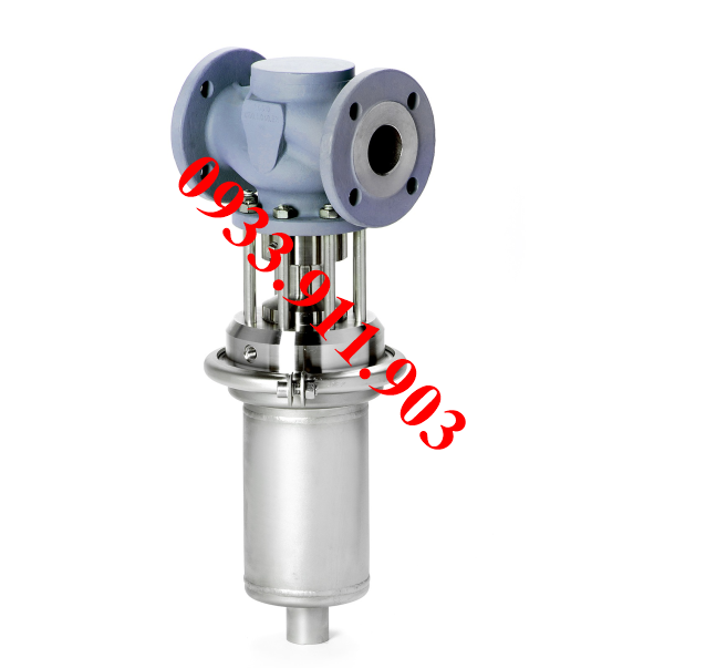
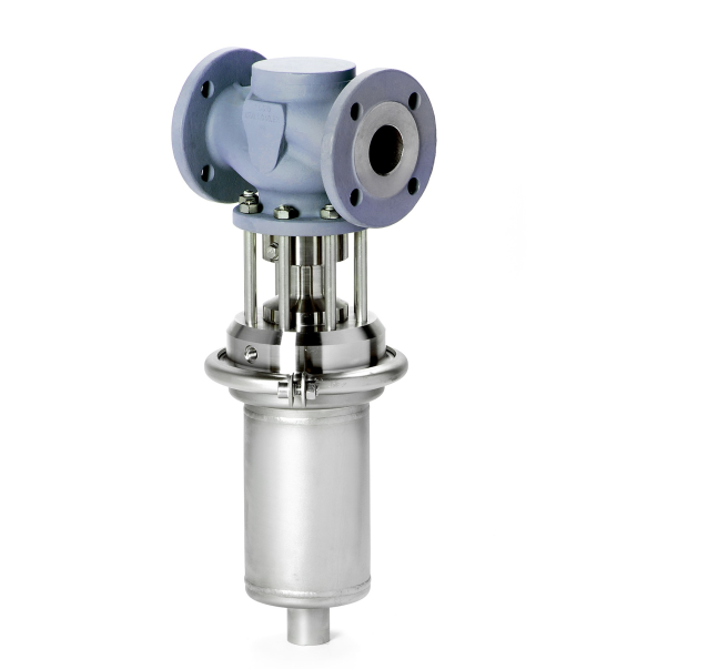
The pressure reducer DM 618Z ASME
is a diaphragm-operated, spring-loaded and balanced proportional valve for high flow rates.
The valve body is made of cast steel. Diaphragm housing, spring cap and internal parts are made of stainless steel 316L.
The valve cone is fitted with a metallic seal.
PRESSURE CONTROL
Pressure reducing valve DM 618 Z ASME
ASME valve for steam
Technical data
| Connection NPS | 1/2 - 4 |
| Class Inlet pressure |
150 - 300 up to 740 / 580 psi |
| up to 51.1 / 40 bar | |
| Outlet pressure | 4 - 145 psi |
|
Cvs value
|
4.2 - 116 US gal/min. 482 °F |
| Medium *RT = -10 °C up to + 50 °C |
Description
Self-acting pressure reducers are simple control valves offering accurate
control while being easy to install and maintain. They control the pressure
downstream of the valve without requiring pneumatic or electrical control elements.
The pressure reducing valve DM 618Z ASME is a diaphragm-operated,
spring-loaded and balanced proportional valve for high flow rates.
The valve body is made of cast steel. Diaphragm housing, bonnet and internal parts are made of stainless steel 316L. The valve cone is fitted with a
metallic seal.
The outlet pressure to be controlled is balanced across the control unit by
the force of the valve spring (set pressure). As the outlet pressure rises
above the pressure set using the adjusting screw, the valve cone moves towards the seat and the volume of medium is reduced. As the outlet pressure
drops, the valve control orifice increases; when the pipeline is depressurised, the valve is open. Rotating the adjusting screw clockwise increases
the outlet pressure.
The valve requires a sense line (to be installed on-site).
These valves are no shut-off elements ensuring a tight closing of the valve.
In accordance with DIN EN 60534-4 and/or ANSI FCI 70-2 they may feature
a leakage rate in closed position in compliance with the leakage classes III
or V.
Standard
» Body made of cast steel 1.0619 (GS-C25 / A216-WCB)
» Diaphragm housing and closed bonnet made from stainless steel 316L
(1.4404)
» Internal parts made of stainless steel
» Leakage line connection and sealed adjusting screw
» Balanced cone for controlling the outlet pressure indipendently from the
inlet pressure
» Sense line connection
» EPDM elastomers
Options
» FKM elastomers
» PTFE protection foil for diaphragm
Please specify on order
| Please specify on order: | |
| » Nominal diameter »C vs / Kvs-value » Body material |
» PT rating » Pressure range » Elastomeres |
Example: DM 618Z ASME, NPS 1, Class 300, Cvs 9.3 US gal/min, 30 - 75
psi, A216-WCB, EPDMTechnical specification
| Cvs values [US gal/min] | ||||||||
| NPS | 1/2 | 3/4 | 1 | 1 1/2 | 2 | 2 1/2 | 3 | 4 |
| min. | 0,9 | 0.9 | 0.9 | 1.2 | 1.2 | 1.2 | 1.2 | 1.2 |
| 4 - 16 psi | 4.2 | 7 | 7 | 31.5 | 40.8 | 52.4 | 58.3 | 64.1 |
| 10 - 145 psi | 5.2 | 9.3 | 9.3 | 31.5 | 40.8 | 93.2 | 104.9 | 116.5 |
| Kvs values [m3/h] | ||||||||
| NPS | 1/2 | 3/4 | 1 | 1 1/2 | 2 | 2 1/2 | 3 | 4 |
| min. | 0.8 | 0.8 | 0.8 | 1 | 1 | 1 | 1 | 1 |
| 0.3 - 1.1 bar | 3.6 | 6 | 6 | 27 | 35 | 45 | 50 | 55 |
| 0.8 - 10 bar | 4.5 | 8 | 8 | 27 | 35 | 80 | 90 | 100 |
| Setting ranges [psi / bar] | ||||
| psi | 4 - 16 | 10 - 35 | 30 - 75 | 65 - 145 |
| bar | 0.3 - 1.1 | 0.8 - 2.5 | 2 - 5 | 4.5 - 10 |
| Reduction ratio (max. p1/p2) | |||
| setting range [psi/bar] |
NPS | ||
| 1/2 - 1 | 1 1/2- 2 | 2 1/2 - 4 | |
| 65 - 145 / 4.5 - 10 | 10 : 1 | 8 : 1 | 5 : 1 |
| 30 - 75 / 2 - 5 | 20 : 1 | 15 : 1 | 10 : 1 |
| 10 - 35 / 0.8 - 2.5 | 30 : 1 | 20 : 1 | 12 : 1 |
| 4 - 16 / 0.3 - 1.1 | 15 : 1 | 11 : 1 | 6 : 1 |
Example: set pressure 10 psi / 0.8 bar
= max. inlet pressure 300 psi (30 x 10) / 24 bar (30 x 0.8).
Attention: The max. allowable operating pressure must be observed!
For more information see the attachment.
| Materials* | ||
| 1 | Body | GS-C 25 1.0619 (A216-WCB), optionally made of stainless steel 1.4408 (CF8M) |
| 2 | Diaphragm housing | Stainless steel 1.4404 (316L) |
| 3 | Bonnet | Stainless steel 1.4404 (316L) |
|
Địa chỉ: 451/25/3A Tô Hiến Thành, P.14,Q.10, TP.Hồ Chí Minh Bản quyền 2006 - 2026 thuộc về chodansinh.netGiấy phép đăng ký Kinh doanh số: 4102048591 do Sở Kế Hoạch và Đầu Tư cấp ngày 28/03/2007  |